Many of today’s precision applications necessitate gears capable of dramatic speed reductions, power densities, and transmission accuracies. Leading choices in these designs include trochoidal and cycloidal gearing as well as gearsets relying on wave-inducing subcomponents having an elliptical or Reuleaux or other polygonal shape.
Trochoidal and cycloidal gearing includes elements that rotate and trace curves around some other element. Cycloids traced by a point on a rolling element’s circumference include epicycloids (for which the element rolls along the outside of a sun gear or other reference component) and hypocycloids for which the element rolls within a ring or other reference component. In contrast, trochoids (and their subtypes) are traced not by a point on the rolling element’s circumference but rather some point within or without. One particularly common subtype of epicyclic gearing is planetary gearing.
Consider a robotic joint employing a motor (running at a few thousand rpm) fitted with gearing for output speeds to 100 times slower. Gearing in such designs also serves to boost acceleration torque for top power density — a priority design objective for SCARAs and collaborative robotics for which the total assembly is essentially a cantilevered mass.

Wave and cycloidal gear options include (from left to right) strain-wave gearing, planocentric and cycloidal gearing, planetary gearing, and dynamic thrusted-tooth gearing.
Recall that conventional gearing used in such designs (including some planetary gearsets) usually exhibit a very small amount backlash. This is often limited to only a few arc-min. (100ths of a degree) and serves to accommodate lubrication and thermal expansion. However, this backlash can in some cases degrade system accuracy by unacceptable amounts. So let’s take a look at other gear options that avoid the issue.
Summary of strain-wave gearing operation
Strain-wave gearing uses the metal elasticity (deflection) of a gear to reduce speed. Key benefits of strain-wave gearing include zero backlash and high power density and positional accuracy.
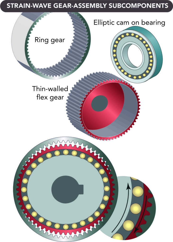
A strain-wave gearset consists of three components: wave generator, flexspline, and circular spline. The wave generator is an assembly of a bearing and a steel disc with an elliptical shape machined to precise specifications. A specialty ball bearing fits around this disc and conforms to the elliptical shape. Most designs attach the wave generator to a servomotor — to serve as the motion input.
The flexspline is a thin-walled steel cup. These cup walls are radially compliant but remain torsionally stiff — because the cup has a large diameter. Manufacturers machine the gear teeth into the outer surface near the open end of the cup … near what one might call the brim.
The flexspline usually serves as the output.

The cup has a rigid boss at one end to provide a rugged mounting surface. The wave generator is inside the flexspline so the bearing is at the same axial location as the flexspline teeth. The flexspline wall near the brim of the cup conforms to the same elliptical shape of the bearing. This conforms the teeth on the outer surface of the flexspline to the elliptical shape. That way, the flexspline effectively has an elliptical gear-pitch diameter on its outer surface.
The circular spline is a rigid circular steel ring with teeth on the inside diameter. It is usually attached to the housing and does not rotate. Its teeth mesh with those of the flexspline. The teeth of the flexspline engage the teeth of the circular spline along the major (long) axis of the ellipse. So there are two areas of meshing made by the ellipse inscribed concentrically within the ring. Roughly 30% of the teeth are engaged at all times — in contrast with six or so teeth engaged at any time for an equivalent planetary-gear set, and one or two teeth for an equivalent spur-gear set.
Recall that backlash is the difference between the space to accommodate the teeth and the tooth width … and this difference is zero in strain-wave gearing. Elastic radial deformation of the strain-wave flexpline (preloaded by the manufacturer against those of the circular spline at the major axis) acts like a very stiff spring to compensate for space between the teeth that would otherwise cause backlash. Preload is set to keep stresses well below the material’s endurance limit.
The pressure angle of the gear teeth transforms the output torque’s tangential force into a radial force acting on the wave-generator bearing. The flexspline and circular spline teeth engage near the ellipse’s major axis and disengage at the minor axis. The flexspline has two less teeth than the circular spline, so every time the wave generator rotates one revolution, the flexspline and circular spline shift by two teeth. The gear ratio is the number of flexspline teeth ÷ (number of flexspline teeth – number of circular spline teeth).
The lightweight construction and single-stage gear ratios (to 160:1) of strain-wave gearing let engineers use the gears in designs needing minimized weight and volume. Even small motors can leverage their large mechanical advantage. Certain tooth profiles (of convex and concave arcs) for strain-wave gearing let more teeth engage — for increased torsional stiffness and torque … as well as a longer MTBF.
Summary of thrusted-tooth gearing operation
Now let’s consider the thrusted-tooth design mentioned earlier. This newer high-torque gearbox offering offers extreme torsional rigidity and zero-backlash operation for applications that need superior precision in output motion. In contrast with other gear offerings that transmit power over lines of contact on gear teeth, meshing gears in the drive make almost full-surface contact. This allows for tooth contact that’s up to 6.5 times that of certain types of conventional involute teeth.
How does it work? In short, the gearbox guides a large array of individual teeth along an internal ring gear. The tooth geometry follows a logarithmic spiral that lets multiple teeth transmit power at once through hydrodynamic contact — covering much larger surface areas than traditional line contact. The result is a gearbox with zero backlash even at the zero crossing. The logarithmic spiral path of the teeth allows for synchronization accuracy that outperforms traditional hollow-shaft drives with comparable outer diameters.
The gearbox also boasts up to 91% efficiency — 18 to 29% better than traditional strain-wave and cycloidal geared arrangements.
As part of a drive system, hydrodynamic tooth contact of the gear drive also delivers high overload capability. Emergency stop torque is 150 to 300% better than comparable systems, and torsional rigidity is to 580% higher … so gearboxes of other designs might need to be up to three times larger to deliver the same torque as a given thrusted-tooth gearbox.
The gear design also allows for a very large hollow-shaft diameter in relation to the outer diameter — to 70% larger in some cases.
Summary of cycloidal gearing operation
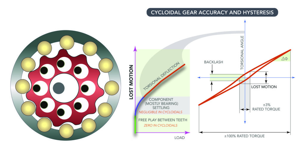
The eccentric rolling-mechanism gearheads known as cycloidal reducers are a type of servo gearing that has an input shaft that drives a bearing assembly. This in turn drives a cycloidal disc (sometimes called a cam) that connects to an output shaft. The cam has lobes or teeth that engage with a cam follower — typically with pin or needle bearings. The eccentric cam rotation induces rotation of an output shaft at a lower speed and higher torque than the input.

The main advantage of cycloidal reducers is their property of zero or near-zero backlash (to 1 arc-min.) which makes for high precision and high accuracy. This is especially in demand where highly precise and accurate positioning is required, for instance in robotic applications, machine tools, and similar applications. Cycloidal reducers also feature rolling as opposed to sliding contact, thus experiencing less overall wear. Some cycloidal speed reducers offer zero backlash by combining a compound reduction cam with a full complement of needle-bearing cam followers.
Because of the pin-and-gear structure, cycloidal gearing maintains continuous and distributed power-transmission contact for higher shock resistance than traditional reducers. In fact, some variations can withstand transitory exposure to quadruple their rated torque. High torque density makes for ratios to 185:1 in reasonable gearbox footprints.
You may also like:
Filed Under: Motion Control Tips


