Pneumatic solenoid valves make it possible to remotely operate and automate equipment, with a range of product and technology options available for upgrading designs.
By Kevin Kakascik and Pat Phillips, AutomationDirect
Pneumatic systems provide one of the essential methods designers can employ to create motion and force for equipment and manufacturing systems. These systems are economical, reliable, and easy to design and maintain They also operate with speed, precision, and force suitable to meet most mechanical requirements.
Basic manual pneumatic components are appropriate for certain situations, but most forms of remote or automatic operation are better implemented with hardwired logic or programmable logic controllers (PLCs). For these electrical and intelligent platforms to interact with the physical pneumatic systems, a solenoid of some sort is typically incorporated.
Designers need to be familiar with several types of solenoid valves and the varying form factors and features available so they can select the right products. In many cases, there is more than one right answer depending on the required action, installation space, and type of automation.
From manual to automatic
Valves are typically used to control the flow of liquids and gases. They may directly control a fluid — such as water, solvent, or anything else used in a production process — or they may be arranged to command more powerful physical actions.

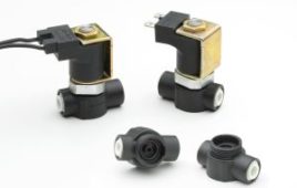
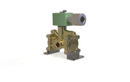
Figure 1. Electric solenoid valves are available in a wide variety of form factors. When installed on equipment or in associated control panels, they make it possible to remotely and automatically operate systems. All figures courtesy of AutomationDirect.
The valve itself can be operated manually or by a physical action, such as a door closing or a person moving a button, pedal, or lever. Many types of basic equipment and processes are designed with manually operated valves managed by operators. But to improve efficiency and safety, it is often desirable to upgrade designs to automatically controlled valves.
For most kinds of automation, a valve needs to be controlled electrically by hardwired circuitry or a PLC. Electric solenoids are the fundamental way to operate valves of all sizes, Figure 1.
An electric solenoid consists of a wire coil arranged around a movable central poppet, plunger, or spool element. It enables an electrical current to create a low force linear motion controlling physical flow. A solenoid-operated valve effectively acts as an amplifier, converting a small electrical signal into a comparatively large physical force.
Medium, small, and miniature valves
Electromagnetics and solenoids can be quite powerful, and they are suitable as the motive force for operating direct-acting medium-sized physical valves of perhaps 0.75-in. pipe diameter, or smaller. This arrangement is fast-acting.
There are also solenoid-operated diaphragm valves, which can be somewhat larger and slower, where the solenoid vents a small pressure port to enable a diaphragm to flex and enable a larger process flow. Even larger valves usually have various valve body mechanisms, which in turn are operated by some external actuator method, although the external actuation often involves solenoids.
For example, a medium-sized solenoid valve can be used directly in a pipeline to control a process fluid in an on/off manner, or the same type of solenoid can control fluid or gas used to move an actuator, which in turn can drive mechanical equipment or a much larger valve.
When a smaller valve is used to operate something larger, it is often called a pilot valve or a directional control valve. Smaller pneumatic solenoid valves, typically used for controlling pressurized gas, are often used to control the actuators of much larger valves. A small solenoid valve is a good choice to minimize the footprint and power consumption needed for a PLC to control valves.
Taking things a step further, there are other form factors that can be a good match for space-limited systems, Figure 2. Miniature versions offer just enough flow in the most compact package possible. Stackable solenoids valves fit together to share air supply connections, saving installation space. Modular arrangements simplify plumbing like the stackable style, as they allow multiple solenoid valves to be installed onto a common manifold.

Figure 2. A wide variety of valve form factors can be used to obtain the best option for each applications. Shown clockwise starting from top center: modular/manifold solenoid valves; miniature manual valve; process solenoid valve; directional control solenoid valve; stackable solenoid valves; modular/manifold solenoid valves.
While many solenoid form factors must be installed within a control panel or other protected location, there are now many components rated for surface-mounting, even in washdown areas. This enables designers to distribute solenoids around a machine with substantial space and cost savings.
Solenoid valves of many different form factors can be employed as a very compact and efficient way of controlling larger equipment.
Flow basics
Designers must size and select a solenoid valve by considering the operating fluid pressure, and the flow necessary to operate the target equipment with the right force and speed. They must also plan for the solenoid valve functionality, or how many actions it must perform.
Most people think of a valve as normally closed (NC) or off, unless it is commanded to open. However, there are many cases where it is desirable for a valve to be normally open (NO) and flowing unless commanded to close. The arrangement of a solenoid valve spring and coil defines whether it is NC or NO. A common mistake often made by designers with a stronger electrical background is that a NC electrical switch allows current to flow while a NC valve stops fluid flow.
Each solenoid valve’s physical fluid connection is called a port. One or more electrical solenoids shift the valve spool into position when commanded. Two-position valves are most common, but three-position valves are also possible. The number of ports and positions defines how many ways a solenoid valve can flow.
For direct-acting process and pipeline solenoid valves, the most common are 2-way valves, which simply turn flow on and off. Also available are 3-way valves, useful for shifting flow between two different destinations.
A 2-way solenoid valve has two ports, so when the valve is closed, the ports are isolated from each other, and when the valve is opened, the fluid can flow between the two connections. A 3-way solenoid valve has a common port, and two other ports we will call A and B. When de-energized, the common port is connected to A, while B is isolated from both. When energized, the common port is connected to B, while A is isolated from both.
Solenoid valves used in pilot service to control fluids to larger actuators can be more complex, and come in arrangements such as:
- 2-port (2-way), 2-position
- 3-port (3-way), 2-position
- 5-port (4-way), 2-position
- 5-port (4-way), 3-position

Figure 3. This diagram shows the internal spool of a 5-port 2-position solenoid valve body, although the electric solenoid itself is not shown. When energized, the solenoid would move the spool to the right to apply pneumatic pressure and extend a cylinder; when de-energized, a spring would move the spool to the left to retract a cylinder. Electric solenoid valves used with PLCs enable the automation of sizable equipment.
Pneumatically connecting the variety of possible solenoid pilot valves to achieve the desired physical outcome, and creating drawings with the proper pneumatic circuit symbols, is a subject unto itself. But it is also closely related to the choice of the associated electrical solenoids, Figure 3.
Solenoids in pilot valves can be single-acting with spring return. This means a spring holds the spool in one position when de-energized (at rest), while the spool moves a single direction to another position when energized.
Or a pilot valve can be double-acting where two electrical solenoids are operated, one at a time, to pull the spool to one position or another. The double-acting spool may be strictly two-position, remaining at whichever position it was pulled once the solenoid is released. Or it may be three-position, where solenoids pull the spool to one position or another, while springs will return the spool to a central position if all solenoids are de-energized.
Smarter solenoids
Solenoids themselves are electrical and can be driven by a hardwired circuit or a PLC output. Some solenoid form factors, especially modular styles, offer prewired and/or connectorized electrical arrangements, simplifying installation and wiring significantly.
Another important advancement is the availability of smart modular valve manifolds, where a single network connection allows the valves to be commanded from a host PLC. This connection is usually some form of standard industrial fieldbus, such as serial Modbus RTU, or an Ethernet protocol like EtherNet/IP. These manifolds may also accept input/output (I/O) modules, and they may provide solenoid valve status information and diagnostics.
Intelligent valve manifolds minimize wiring, especially if pneumatics and remote I/O can be combined into one consolidated package on a machine. Modular components make it possible for designers to create advanced equipment control systems in the most compact possible installation.
Making the move
With all these details in mind, how do designers decide when and how much it makes sense to upgrade manual operations to automatic functionality? Two main factors are when safety can be improved, or when efficiency can be increased.
Safety is enhanced when automation and solenoid valve-controlled devices allow operators to work remotely from the equipment. Also, adding hardwired or PLC-connected sensors makes it possible to notify operators of equipment conditions, and even proactively establish interlocks to prevent improper operation.
Converting manual equipment to automated designs usually upgrades operating speed and throughput, and it can pay dividends down the road if diagnostic provisions are built-in, such as alarms to indicate a problem.
Another cost consideration is how stackable and modular solenoid valves, or surface-mount styles, can shift more of installation effort to controlled shop conditions. Because these form factors minimize the amount of plumbing and electrical/network connections, they can be easily disconnected after installation and testing at the shop. This makes it more convenient to ship automated equipment and speed-up installation in the field.
For designers of equipment currently using manual pneumatics, there are many capable and economical options for upgrading using solenoid valve technologies. Working with a supplier who offers a full portfolio of solenoid options, electrical components, PLCs, and associated accessories can help designers determine the best upgrade path for their applications.
Filed Under: Pneumatic equipment + components, Solenoids


