This article was contributed by Garrett Clyma, CFD Engineer at Flow Science.
Melt pool flow dynamics is a critical and often overlooked aspect of the metal 3D printing process. Changes in heat input, powder, and alloy properties directly impact the melt pool evolution, affecting a part’s quality and mechanical properties. Since the melting process occurs at the microscale in space and time, it is quite difficult to do in-situ measurement and characterization.
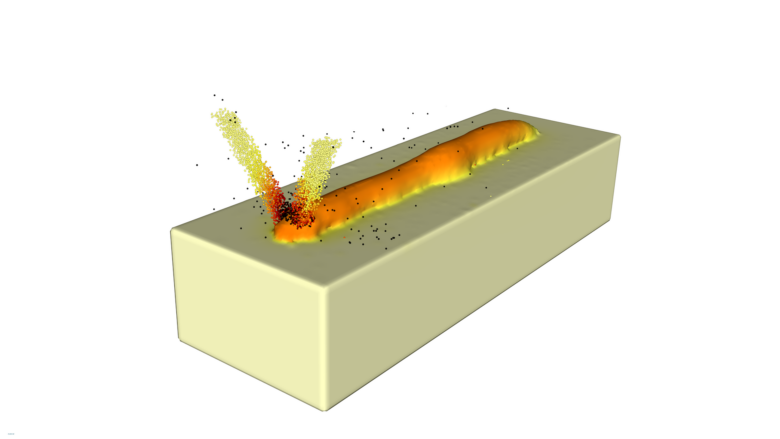
Computational fluid dynamics (CFD) simulation provides a detailed view of the physical phenomena during 3D printing. It directly models the melt pool fluid dynamics as the laser interacts with the metal powder. CFD software provides a level of control and accuracy that cannot be replicated by measurement or lower-fidelity models.
More than 40 years ago, C.W. Hirt, the founder of Flow Science, established a computational technique for tracking the evolution of an interface between two fluids with drastically different densities — such as the free surface between air and water. This technique, called the Volume of Fluid (VOF) method, is the foundation of Hirt’s commercial CFD software, Flow-3D. Since its original development, Flow-3D and the VOF method have been used in research and design processes for a range of applications, such as dam spillways, high-pressure die castings, and inkjet microfluidics.
In the last decade, Flow Science engineers applied the VOF method to melt pool dynamics in the metal AM industry. The result was Flow-3D AM, which combines the fluid solver in Flow-3D with laser physics and powder dynamics to model the full process of powder settling, spreading, melting, and solidification in laser powder bed fusion (LPBF) and directed energy deposition (DED), along with the dynamics of non-laser-based AM processes, such as binder jetting and material extrusion.

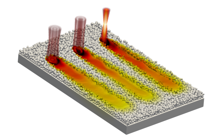
In LPBF, metal powder is spread over a build plate and subsequently melted by a laser beam into a specific pattern. The process is repeated hundreds or thousands of times to build a part layer by layer. Using the discrete element method (DEM), engineers can simulate the powder settling and spreading process in detail by accounting for the particle collisions, powder size distribution, and geometry effects of the blade or roller that spreads and packs the powder layer.
Once the powder bed is generated, a CFD simulation models the laser-material interaction during the melting process. To do this accurately, engineers must account for the large body of relevant physics, including the viscosity of molten metal, surface tension, heat transfer, laser reflection and absorption, phase change, recoil pressure, and solidification, among others. Clearly, there is a lot going on.
The norm in metal additive manufacturing is to use thermomechanical simulations to predict part-scale stresses and distortions. While useful, these models are lower fidelity in nature and cannot accurately predict track geometry and defects, such as keyholing, balling, porosity, and lack of fusion, which are all related to the evolution of the melt pool. Process parameters must be optimized to reduce the formation of defects and provide a low scrap rate for additively manufactured parts to compete in the industry.
By adjusting the process input parameters, such as laser power and speed, scan path, beam shape, and powder size distribution, in the software, researchers and engineers receive deeper insights into the physical phenomena at play behind the process issues, which can then drive the development of process parameter windows.

Keep in mind that high-fidelity modeling is limited by its high computational cost. The large number of physics being solved for is computationally intensive, meaning that simulations are limited to the mesoscale — track lengths on the order of millimeters and single-digit layers. The software also does not directly solve for stress and microstructure formation, although information can be gained about both using the accurate thermal data from a simulation in other models.
Despite these limitations, the value of the information obtained using high-fidelity modeling tools like CFD is an order of magnitude higher than that gained from lower-fidelity, part-scale tools. But since the AM process involves multiple scales, process design must rely on multiple tools. As of now, there is no modeling tool that can do everything engineers need, so integration is key. Each company or university uses different measurement, simulation, and in-situ process tools, and it is imperative that these tools can communicate with each other.
“The overwhelming number of process parameters in AM calls for automated optimization tools based on physics-driven simulations,” said Marcin Serdeczny, Ph.D., CFD engineer at Flow Science. “To drastically reduce the cost and time of new developments, we can no longer rely on a trial-and-error experimental approach. Tools like Flow-3D AM are exactly a step in that direction.”
As the metal 3D printing industry advances, high-fidelity simulation tools will play an even greater role in manufacturing. With continued advancements in computing power, material science, and machine learning, the accuracy and capabilities of these simulation tools will only improve.
Flow-3D
www.flow3d.com
Filed Under: 3D CAD World


