New technologies boost the reliability and efficiency of vertical motion designs (including an array of lifts and hoists) for setups of various sizes. In the feature, we get input from one industry expert on the subject and then outline five key parameters that dictate what makes linear actuators suitable for lifting.
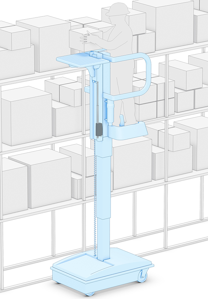
Vertical motion designs (as this lift application powered by Thomson WhisperTrak electric linear actuators) must work against and with gravity. That has broad-reaching implications for force ratings, lubrication methods, and more.
Mounting orientation — especially when vertical — greatly influences which types and sizes of linear actuators are sufficient for a motion systems. Some actuators (because of their guide design) can support higher downward or liftoff loads than side loads; others can handle pitch and yaw moments more than roll moments. These factors dictate which linear actuators can run in vertical builds. The mechanical axis drive also determines actuator suitability for vertical setups. Ball and leadscrews outperform belts and linear motors in carrying loads vertically, but aren’t without limits.
To get more details on these special challenges of vertical applications — for everything from small jacks to large installations for gantry robots in AS/RSs — we spoke with Travis Gilmer of Thomson Industries — product line specialist for industrial linear actuators. Here’s what he had to say.
What are some technologies to increase the efficiency of vertical linear actuator applications?
Gilmer: Typically, a vertical lift must resolve two components of force — lifting force and side-load (or moment load). Technologies to handle those loads range from simple pulley or winch-type lifts and hoists (which only handle the vertical load) to more complex and complete lifting columns that handle both lifting force and side-loads. More complete technologies make for more efficient lifting action. Further integration of electronics (such as feedback sensors and controls) into older-generation lifting devices allows for turnkey setup for controlling the lift in a vertical application.
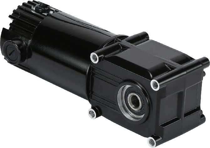
This is a Bison Gear and Engineering PowerSTAR hypoid right-angle gearmotor. It works in an array of applications — including vertical lifts for mobility designs.
What are the unique challenges in terms of forces and acceleration on these vertical lifts?
Gilmer: One must consider both the load of what is being lifted vertically and any side or moment loads that the application encounters along the lift. Consider an ergonomic adjustable desk. The application calls for a vertical lift. One challenge here is whether or not the load on the desk is evenly distributed. Lifting from the center may provide excessive moment loading and lead to failure, while lifting from both sides (with two devices) presents offset loading. The latter can in turn cause uneven lifts.
Secondly, there may be forces acting on the desk surface after or during the lifting process that introduce more uneven loading and moment loads for the lifting devices to resolve. This is why one typically sees bearing-supported actuation doing this type of lift. Actuators inside the linear-bearing structure handle the vertical load, while the linear bearing supports keep the structure level and stiff in the presence of uneven loading or side-loads. Keeping multiple devices in sync (given various accelerations and forces due to offset loading) is likely the most common problem in this application type.
What kinds of sensing feedback are common in such setups?
Gilmer: The most common design uses an encoder that communicates position feedback as a pulse-train signal relative to the home or starting position of the lifting device. One caveat here: It’s important to zero out the encoders before a lift is enacted, or else there may be uneven lifting or inaccurate positional feedback.
What are common features to ensure safety in vertical setups?
Gilmer: A common safety measure is another integrated control called either electronic load sensing or current sense. With this, an onboard controller monitors current draw on the lifting device and stops movement if an overload is encountered — or if an end-of-travel limit is reached. Stopping motion in these scenarios ensures the device is operating only when told or when it should move given the application parameters. The load-sensing devices can be calibrated for alternate applications — for example, to allow more current in one direction (lifting) and less in another (lowering) to prevent any sort of pinching or damage to anything that may get caught underneath what’s being lifted. Once the movement is done, designs can incorporate static holding brakes to prevent the load from moving — even when power is lost. Oftentimes these brake designs allow for a larger load than the lift can handle (referred to as static loading capability), which gives the application an appreciable margin of safety.
What’s behind the increased use of electric actuators in vertical lift applications?
Gilmer: Electric actuators typically resolve the vertical and lifting forces in these applications. They’re responsible for moving and ultimately holding loads in place after moves are done. The aforementioned controls and electronics are now integrated into electric linear actuators to ensure efficiency. Once lifting forces are resolved, all that’s eft is to support the actuator with bearing surfaces (linear rails or guides) to prevent the side-loading that can potentially damage the electric actuator.
The design parameters Gilmer describe above can be outlined quantitatively as well. Consider the special case of lifting with a fully integrated actuator (including linear bearing supports — going beyond free-hanging hoist and crane setups) on a moderately sized axis. As we’ll now outline, complete analysis of such vertical linear-actuator applications requires consideration of five design factors.
Note that the following presents concepts adapted from the feature by Danielle Collins: Five things to consider in vertical applications. Read more at the link.
First parameter: Vertical load orientation
Load placement and orientation dominate actuator setup in vertical arrangements. Actuators in such axes (whether pulling, pressing, or transporting the load) work against gravity during lifts and are assisted by gravity during declines. So, load on the motion design varies with these two motions. This affects guide-bearing and drive-mechanism life in addition to required motor torque. What’s more, the force of gravity on the load when starting and stopping will influence the inertia of the system, which also plays a role in both actuator selection and motor sizing.
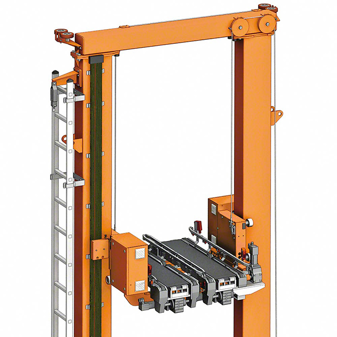
This Interlake Mecalux Unit Load AS/RS is a versatile vertical design —compatible with myriad warehouse pallet sizes and load racks of single or double-depth capacity. Such vertical warehouse automation boosts reliability and capacity while allowing direct access to each pallet.
Note: Vertical applications benefit from the use of two bearing blocks on each guide rail to help the assembly support pitch and yaw moment loads during acceleration and deceleration. What’s more, actuators with two guide rails in parallel let the actuator handle roll moments that arise from unevenly distributed loads or external forces due to other processes. Wherever space allows, choose actuators that use twin guide rails with two bearing blocks each.
Second vertical-motion parameter: Buckling load
When using a ballscrew or leadscrew in a vertical application, the full load is experienced as an axial force, which can cause the screw to bend and, eventually, buckle under the load. The buckling load depends on the screw’s root diameter, unsupported length, and end-bearing arrangement. The end bearing arrangement significant impacts buckling load. More rigidly fixed screw assemblies have higher permissible buckling load. So a screw with a fixed-fixed bearing arrangement has 16 times the permissible buckling load than that of a screw with fixed-free end mounting:

Where Fc = Maximum compressive load, N; fb = End-bearing correction factor; d1 = Root diameter of screw, mm; and L = Unsupported length, mm. Loaded screws are in tension where the fixed bearing is top. This prevents excessive compressive forces on the screw. Most ball or leadscrew actuators have a fixed bearing on the driven (motor) end. That said, check the bearing arrangement and ensure the actuator is mounted so its fixed bearing is up.
Third parameter: Backdriving during drops
Screws are more suitable than belts or linear motors in vertical motion axes because they can prevent loads from catastrophically crashing during power loss. That said, screws with lower internal friction and certain lead angles can back drive. (Note that leadscrews are less efficient so are less likely to backdrive.) Quantitatively speaking, the likelihood that a screw assembly will backdrive is dictated by backdriving torque versus the assembly’s friction force — including nut drag torque as well as seal and end-bearing friction. If backdriving torque is less than assembly friction, the load probably won’t cause backdriving:

Where Tb = Backdriving torque, Nm; F = axial load, N; P = Screw lead, m; η2 = reverse efficiency — 0.8 to 0.9 for ballscrews. Here, efficiency when backdriving is often lower than that of typical setups. Check manufacturer specifications for efficiency.
Fourth parameter: Lubrication of vertical motion designs
Some linear bearings and actuators have lubrication ports on multiple sides to accommodate access where obstacles impede access to one or more ports. Sometimes assembly orientation also dictates which lubrication ports are usable. Because gravity makes it challenging to keep upper linear-guide tracks or uppermost screw raceways lubricated, manufacturers usually outline special lubrication guidelines for vertical strokes. (Usually use of oil is discouraged.)
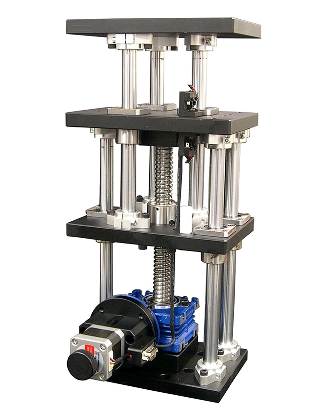
AT20-100 vertical-lift stages from Optimal Engineering Systems (OES) are high-precision stages for moving heavy loads. A 120 x 180 mm drilled and tapped platform has a vertical travel of 100 mm; 5 µm repeatability; 3.315 µm resolution; and 15 µm positioning accuracy. A precision-ground leadscrew, linear bearings, and rigid-box elevator construction maintain smooth motion that stays parallel to the mounting surface. Applications include testing, inspection, assembly, sampling, drilling, and machining. The stage is black-anodized aluminum alloy and steel shafting and weighs 10.5 kg. A two-phase NEMA stepper pairs with the leadscrew to deliver load capacity to 50 kg without concern for cantilevered loads.
What’s more, many assemblies that use grease lubrication have metered lubrication pathways to get the grease to critical internal surfaces — especially those at the top of the machine axis.
Fifth parameter: Contamination
Vertically oriented actuators tend to shed contamination and moisture, so are less prone to corrosion than those in horizontal arrangements. That said, light particulates of fiberglass and ceramic are more likely to stick to linear-bearing surfaces and get pushed by end seals into areas of contamination buildup — which increases the odds of ingress in the linear bearings. One solution is linear guides with both front and side seals. Another is actuators with sealing or covering mechanisms (preferably full-contact seals and not just cover plates) for protection against liquids and particulates.

ABM Drives offers myriad travel motors and drives for hoists and cranes. A Profi-Line offers two travel speeds; pole-switching motors (8/2-pole) with special windings and rotors allow soft starts. Applications include vibration-free transport of sheet-metal coils and moving components for assembly. In contrast, ABM’s Automation-Line motors deliver variable speeds and pair with inverter drives for programmable acceleration and deceleration ramps. This makes for exceptionally soft starts and braking to minimize load swings. Automation-Line motor-drive setups are suitable for motion designs that handle glass, paper coils, and molds and other large dies.
ABM Drives | www.abm-drives.com • Optimal Engineering Systems (OES) | www.oesincorp.com • Interlake Mecalux | www.interlakemecalux.com • Bison Gear and Engineering | www.bisongear.com • Thomson Industries | www.thomsonlinear.com
Filed Under: Warehouse automation, Linear Motion Tips




Tell Us What You Think!